|
Language

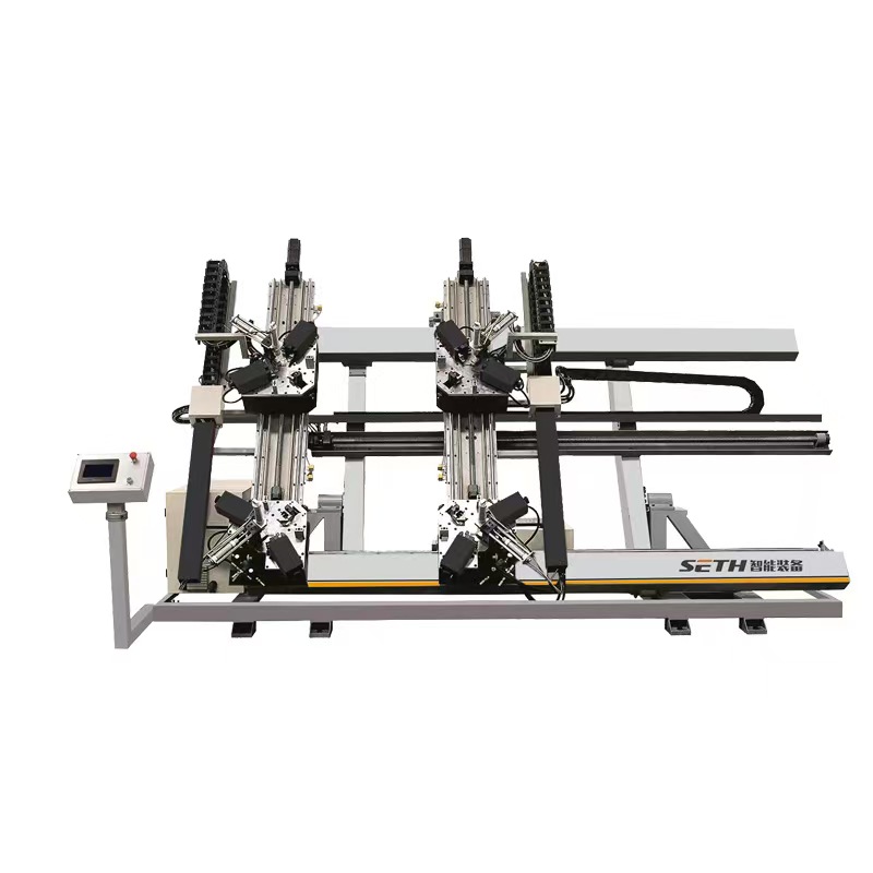
CNC Four Head Corner Crimping Machine
Four-Station Simultaneous Processing
Micron-Level Precision Control
Intelligent Adaptive Function
Safety and Convenience Design
CNC System with high efficency
Product Details
CNC Four-Head Corner Joining Machine:
Core Equipment for Efficient and Precision Processing of Doors and Windows

In the field of door and window manufacturing, the corner joining process directly determines the sealing performance, flatness, and service life of the products. As a core piece of equipment integrating automation and high precision, the CNC four-head corner joining machine eliminates the pain points of low efficiency and poor accuracy associated with traditional corner joining machines through its four-station simultaneous processing capability. It has become standard equipment in mid-to-high-end aluminum alloy and thermal break aluminum door and window production lines.
I. Core Advantages and Application Scenarios
1. Key Technical Highlights
Four-Station Simultaneous Processing: Utilizing independent CNC systems to control four corner-joining units, it simultaneously processes all four corners of door/window frames. This achieves 100% efficiency improvement over traditional dual-head machines, with single-shift production capacity reaching 800-1200 units (based on standard 600×800mm window frames).
Micron-Level Precision Control: Equipped with imported servo motors and ball screw transmission mechanisms, corner pressure (0-30kN) and corner depth (0-5mm) are digitally adjustable. Angle deviation ≤0.1°, post-cornering diagonal error ≤0.5mm/m, meeting high airtightness window/door processing standards.
Intelligent Adaptive Function: Built-in pressure sensors and vision positioning system automatically detect profile thickness (1.4-2.0mm) and corner bracket specifications, dynamically adjusting corner joining parameters to prevent profile deformation or loose joints. Compatible with mainstream 50-120 series door/window profiles.
Safety and Convenience Design: Features dual photoelectric protection devices and an emergency stop button, achieving IP54 protection rating. The ergonomic tilted control console integrates a 10-inch touchscreen for one-touch parameter setup and fault diagnosis, enabling new operators to master operation within 30 minutes.

2. Applicable Scenarios
Batch processing lines for medium-to-large door/window manufacturers (e.g., project doors/windows, custom home doors/windows);
High-precision corner joining for system doors/windows and passive doors/windows;
Corner joining of large-size profiles like aluminum curtain wall frames and sunroom frameworks.

II. Standardized Usage Method
1. Pre-Operation Preparation (5 minutes)
Verify power supply (380V three-phase five-wire) and air source (0.6-0.8MPa) functionality. Confirm pressure gauge and voltmeter readings within standard ranges;
Clear work surface and corner joining unit, removing debris. Inspect corner joining blades and positioning blocks for integrity, ensuring no wear or deformation;
Turn on the main power switch and touchscreen power supply. Enter the operating system, select “Parameter Reset,” and proceed to the processing interface after the self-test completes (all indicator lights turn green).
2. Parameter Settings (First Use or Profile Change)
In the “Profile Parameters” interface on the touchscreen, input the profile width, height, wall thickness, and corner bracket model (e.g., 140/160 type).
Enter the “Corner Joining Parameters” interface to set: - Joining pressure (15-20kN for standard profiles, 22-28kN for thick-walled profiles) - Joining time (1.5-3 seconds) - Press-in depth (1.2-2mm)
Click “Save Parameters” and perform a test run: Insert scrap profiles, initiate “Single Cycle Test,” and inspect the corner joining results. If excessive gaps or profile indentations occur, fine-tune the pressure and depth parameters.
3. Batch Processing Operation (Approx. 30 Seconds per Window/Door Unit)
Place pre-assembled corner-coded window/door frame blanks (pre-coated with corner-joining adhesive) steadily onto the workbench positioning blocks, ensuring profiles tightly contact the positioning surfaces;
Press the “Auto Positioning” button. The equipment's vision system calibrates the window frame position; an indicator light illuminates upon successful positioning;
Simultaneously press the “Start” buttons on both sides of the control panel (safety interlock design). The machine automatically initiates the corner joining process: four corner joining units advance synchronously → press and join corners → hold pressure for 1-2 seconds → units reset;
Upon completion, the machine emits an audible alert. Manually remove the window frame, inspect corner flatness and seal integrity. Qualified frames proceed to the next process; unqualified frames require parameter troubleshooting and reprocessing.
4. Shutdown Procedure
After completing daily processing, clean residual corner sealing adhesive and aluminum shavings from the work surface; close the air supply valve.
Select “Equipment Shutdown” on the touchscreen; after the system saves parameters, turn off the touchscreen power.
Disconnect the main power switch and complete the equipment operation log (recording processing quantity and fault details).

III. Maintenance Plan (Extending Equipment Lifespan to 8-10 Years)
1. Daily Maintenance (10 minutes before/after daily processing)
Cleaning: Use compressed air to blow away aluminum shavings from the corner joining unit, guide rails, and sensor surfaces. Wipe the touchscreen and workbench with a cotton cloth to prevent dust from entering the equipment interior.
Lubrication: Apply 46# anti-wear hydraulic oil to the guide rail lubrication points (marked “oil cup”) once per shift to ensure smooth guide rail transmission.

Inspection: Check
Inspect the miter cutter blades for nicks, check if the positioning blocks are loose, and verify there are no air leaks in the pneumatic hoses. Replace or tighten any components found defective.
2. Weekly Maintenance (1 hour)
Remove the miter cutter for sharpening (use 800-grit sandpaper to repair minor wear). Replace the blade if wear exceeds 0.3mm (recommend keeping 2-3 spare miter cutters on hand).
Inspect the servo motor connection cables and grounding lines for secure fastening. Clean dust from the motor cooling vents.
Test the photoelectric safety device: Trigger the protection by covering the sensor to confirm the equipment stops immediately. Replace the photoelectric sensor if it fails.
3. Monthly Maintenance (2 hours)
Open the side cover to inspect the tightness of ball screws and synchronous belts. The synchronous belt should deflect 10-15mm when pressed; adjust the tensioner if too loose or tight.
Replace the hydraulic system filter (model must match equipment specifications). Top up hydraulic oil to the oil level line (replace all 46# anti-wear hydraulic oil when level drops below 1/3).
Calibrate corner assembly accuracy: Test post-assembly angle deviation using standard gauge blocks (0.01mm precision). If out of tolerance, enter the “Accuracy Calibration” interface to adjust servo motor parameters.
4. Annual Overhaul (Professional Operation, 1 Day)
Completely disassemble the corner assembly unit and replace worn bearings and seals (use original manufacturer parts recommended);
Inspect the operating parameters of the CNC system and servo drives, update system firmware to the latest version;
Apply rust prevention treatment to the entire equipment, spray rust-preventive oil (non-machined surfaces), check the machine body levelness, calibrate with a level, and tighten the anchor bolts.
IV. Common Faults and Solutions
Fault Symptom
Possible Causes
Resolution Measures
Gap at corner after assembly
1. Insufficient corner assembly pressure; 2. Excessive clearance between corner bracket and profile
1. Increase corner assembly pressure (+1 kN per increment, not exceeding 30 kN); 2. Replace with appropriately sized corner brackets
Equipment fails to start
1. Insufficient air pressure/voltage; 2. Photoelectric sensor obstructed; 3. Emergency stop button not reset
1. Check air supply/power source; 2. Clear sensor obstructions; 3. Rotate emergency stop button to reset
Excessive wear on corner joining cutter
1. Inadequate lubrication; 2. Profile hardness exceeds specifications; 3. Cutter blade material mismatch
1. Enhance guide rail lubrication; 2. Test profile hardness (must ≤120HB); 3. Replace with high-speed steel corner cutting tool
Touchscreen unresponsive
1. Poor power connection; 2. Touchscreen malfunction
1. Inspect power cable connectors; 2. Power off and restart; if still unresponsive, contact manufacturer for repair
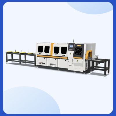
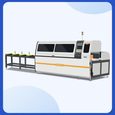
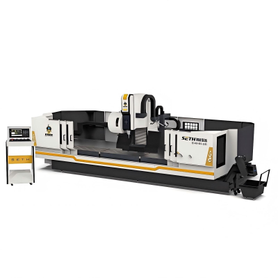
Product form
Related Products
Related News
Popular products
Submitted successfully
We will contact you as soon as possible
Close